Question-and-Answer Resource for the Building Energy Modeling Community
| | 1 | initial version |
I think you've mixed up the concept of where the AirLoop's supply/demand inlet & outlet nodes are located. The AirLoopHVAC object is defining the inlet node and outlet node as:
For example, you're currently defining the AirLoop's Supply Outlet Node as the inlet node to the zone splitter and supply path -- that should instead be the AirLoop's Demand Inlet Node.
!- AirLoopHVAC:ZoneSplitter (for supply air)
AirLoopHVAC:ZoneSplitter,
  Main Supply Splitter,           !- Name
  AHU DEMAND INLET NODE,     !- Inlet Node Name (UPDATE for AirLoop's Demand Side Inlet Node)
  Zone Inlet Node;                !- Outlet 1 Node Name

!- AirLoopHVAC:SupplyPath (routing supply air)
AirLoopHVAC:SupplyPath,
  Main Supply Path,        !- Name
  AHU DEMAND INLET NODE,  !- Supply Air Path Inlet Node Name (UPDATE for AirLoop's Demand Side Inlet Node)
  AirLoopHVAC:ZoneSplitter, !- Component 1 Object Type
  Main Supply Splitter;    !- Component 1 Name
That's one out of various fixes you need to make.
In the EnergyPlus Input Output Reference section describing output variables for AirLoop's, refer to this marked up image.
| | 2 | No.2 Revision |
I think you've mixed up the concept of where the AirLoop's supply/demand inlet & outlet nodes are located. The AirLoopHVAC object is defining the inlet node and outlet node as:
For example, you're currently defining the AirLoop's Supply Outlet Node as the inlet node to the zone splitter and supply path -- that should instead be the AirLoop's Demand Inlet Node.
!- AirLoopHVAC:ZoneSplitter (for supply air)
AirLoopHVAC:ZoneSplitter,
  Main Supply Splitter,           !- Name
  AHU DEMAND INLET NODE,     !- Inlet Node Name (UPDATE for AirLoop's Demand Side Inlet Node)
  Zone Inlet Node;                !- Outlet 1 Node Name

!- AirLoopHVAC:SupplyPath (routing supply air)
AirLoopHVAC:SupplyPath,
  Main Supply Path,        !- Name
  AHU DEMAND INLET NODE,  !- Supply Air Path Inlet Node Name (UPDATE for AirLoop's Demand Side Inlet Node)
  AirLoopHVAC:ZoneSplitter, !- Component 1 Object Type
  Main Supply Splitter;    !- Component 1 Name
That's one out of various fixes you need to make. The main being adding a new node name for the Zone Return Air that is different from the AirLoop's Demand Outlet Node (different nodes located at the inlet and outlet of the Zone Mixer).
In the EnergyPlus Input Output Reference section describing output variables for AirLoop's, refer to this marked up image.
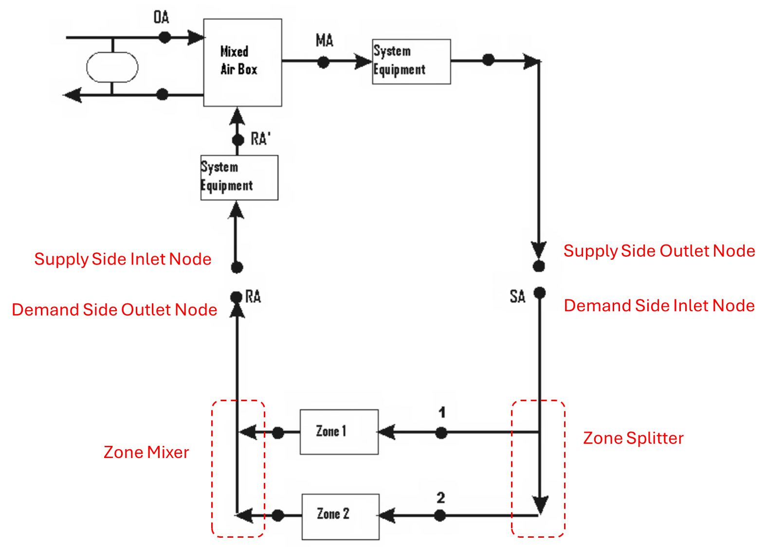
| | 3 | No.3 Revision |
I think you've mixed up the concept of where the AirLoop's supply/demand inlet & outlet nodes are located. The AirLoopHVAC object is defining the inlet node and outlet node as:
For example, you're currently defining the AirLoop's Supply Outlet Node as the inlet node to the zone splitter and supply path -- that should instead be the AirLoop's Demand Inlet Node.
!- AirLoopHVAC:ZoneSplitter (for supply air)
AirLoopHVAC:ZoneSplitter,
  Main Supply Splitter,           !- Name
  AHU DEMAND INLET NODE,     !- Inlet Node Name (UPDATE for AirLoop's Demand Side Inlet Node)
  Zone Inlet Node;                !- Outlet 1 Node Name

!- AirLoopHVAC:SupplyPath (routing supply air)
AirLoopHVAC:SupplyPath,
  Main Supply Path,        !- Name
  AHU DEMAND INLET NODE,  !- Supply Air Path Inlet Node Name (UPDATE for AirLoop's Demand Side Inlet Node)
  AirLoopHVAC:ZoneSplitter, !- Component 1 Object Type
  Main Supply Splitter;    !- Component 1 Name
That's one out of various fixes you need to make. The main being adding a new node name for the Zone Return Air that is different from the AirLoop's Demand Outlet Node (different nodes located at the inlet and outlet of the Zone Mixer).
In the EnergyPlus Input Output Reference section describing output variables for AirLoop's, refer to this marked up image.image. Note that each dot along the line diagram is a unique node in the air system, I've just labelled the four nodes set in the AirLoopHVAC object.


