DaylightingDevice:Tubular Increases Lighting Power

Here are 3 idf files for a virtual office tower with different daylighting control settings. Their version is 8.9.0.
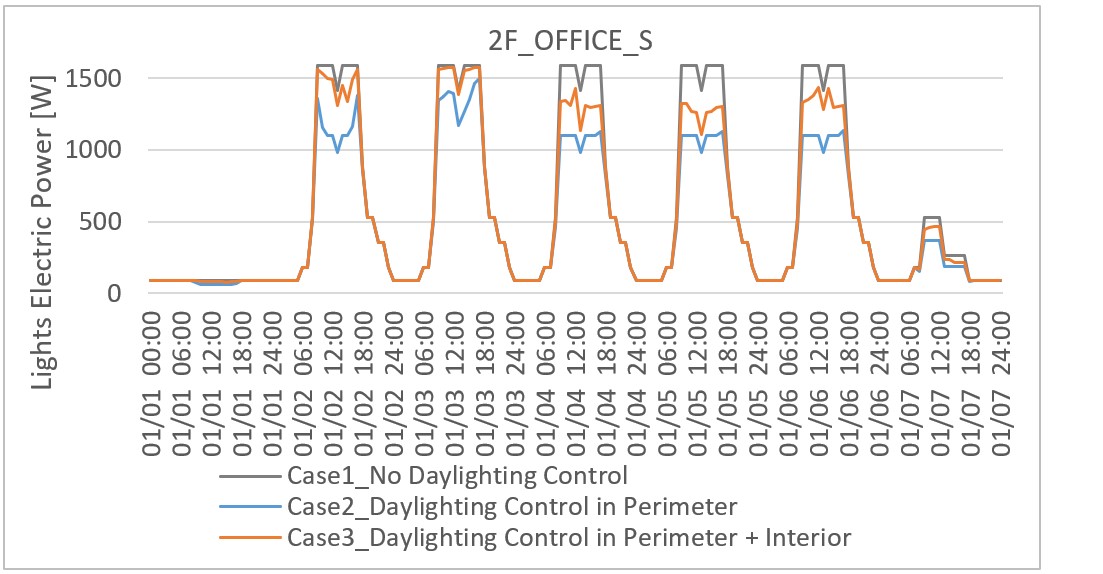
- Case1: No daylighting control
- Case2: Daylighting control in perimeter area
- Case3: Daylighting control in perimeter area and interior area with
DaylightingDevice:Tubular
Case3 was created by adding DaylightingDevice:Tubular to Case2. However, lighting power in Case3 is higher than that in Case2. This is the problem. I don't know why.
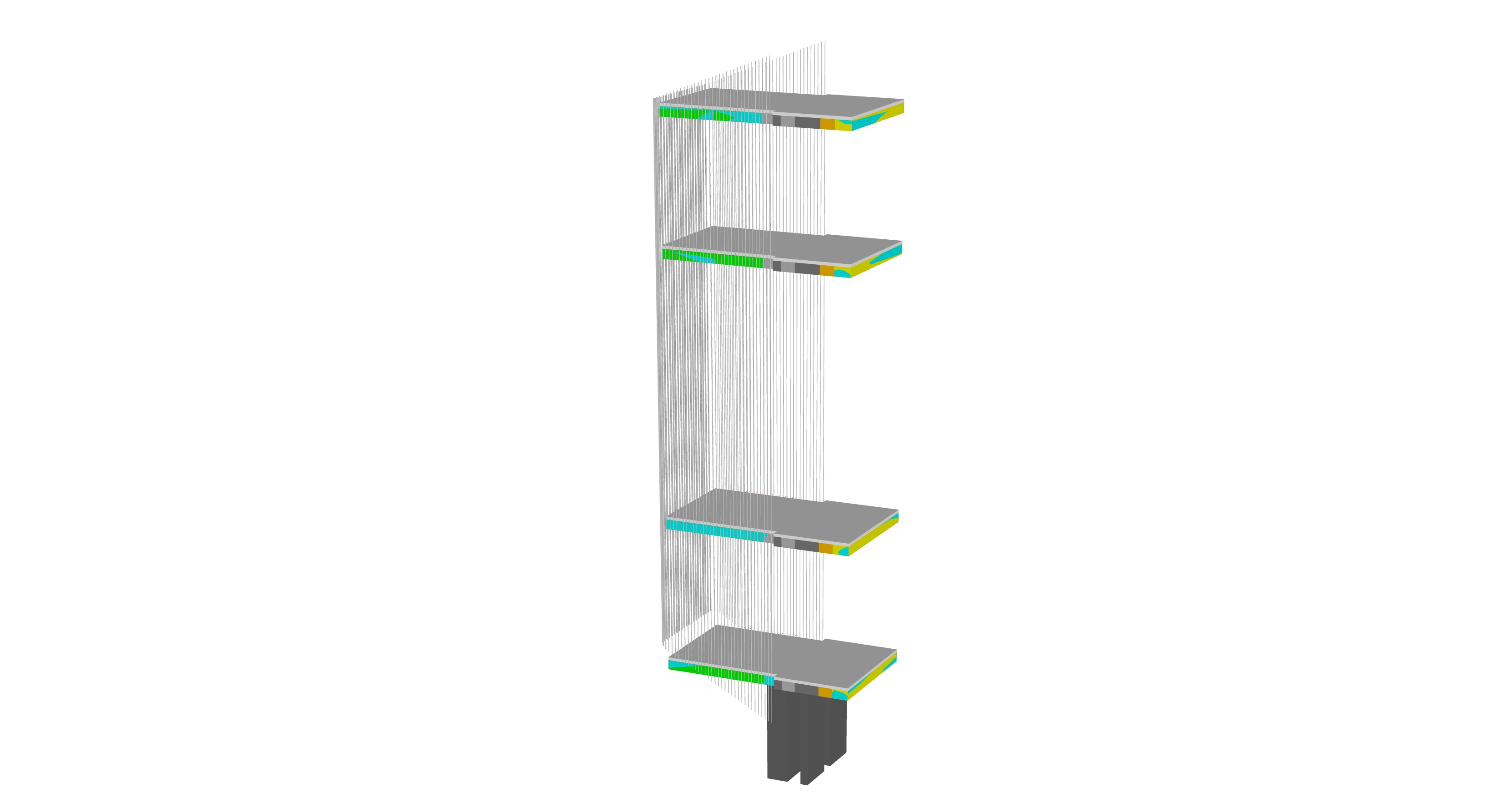
This is the 3D model. Only typical floors are modelled and multiplied. Vertical fins cover around the façade.
DaylightingDevice:Tubular in this model is not used in the usual way. Domes are not on the rooftop but on the wall. They are vertical. Diffusers are on the ceiling. The dome and the diffuser are not in a straight line. This system is not DaylightingDevice:Self, but more like DaylightingDevice:Tubular. Please refer to the sketch below.
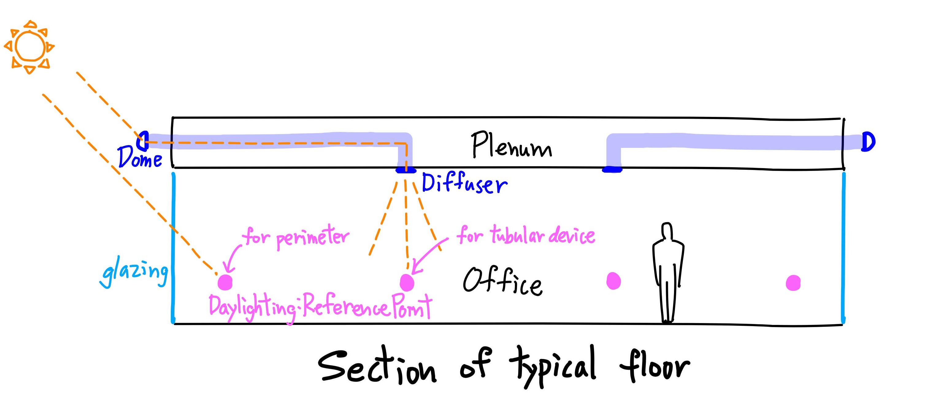
The increase of lighting power might be due to this unusual modelling, but I don't know what is actually not allowed in EnergyPlus.
DaylightingDevice:Tubular is in Office_N and Office_S on each floor. Perimeter area and Interior area are not separated. So, one zone has Daylighting:ReferencePoints for both exterior glazing and DaylightingDevice:Tubular. The simulation result looks as if DaylightingDevice:Tubular is offsetting the lighting power reduction in the perimeter area. It's weird.
Does anyone have any idea why DaylightingDevice:Tubular increases lighting power?
P.S.
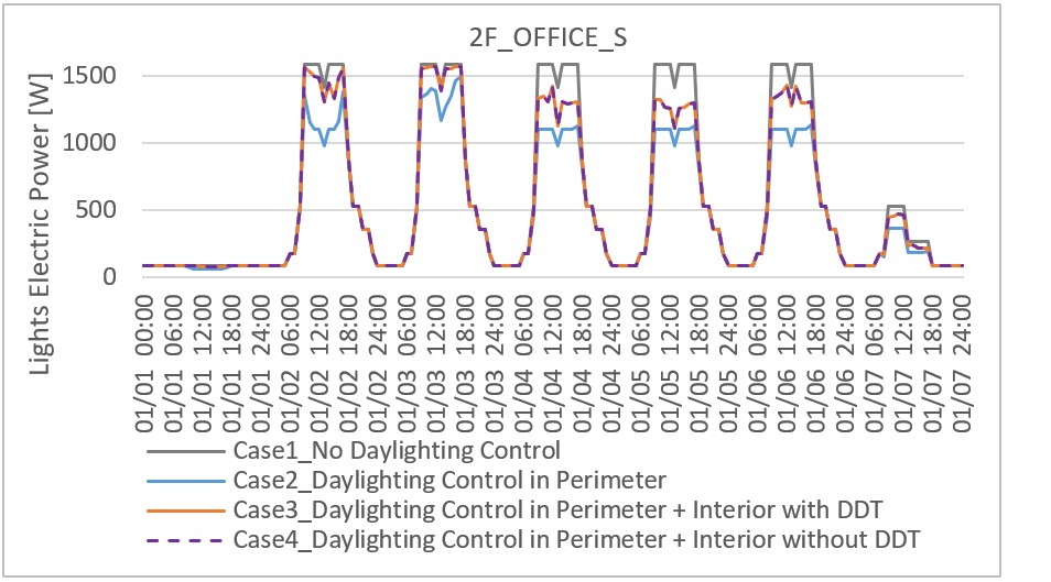
Following Aaron's advice, I ran one more case:
- Case4: Daylighting control in perimeter area and interior area without
DaylightingDevice:Tubular
Case3 and Case4 have almost the same lighting power.
Daylighting:ReferencePoint in intereior area is right under the diffuser of DaylightingDevice:Tubular, but it seems that my dome and diffuser are too small to get enough daylight.
Thus Daylighting:ReferencePoint is irrelevant. Daylighting:ReferencePoint added to interior area interferes with the original Daylighting:ReferencePoint in perimeter area. But I don't know why this happens.
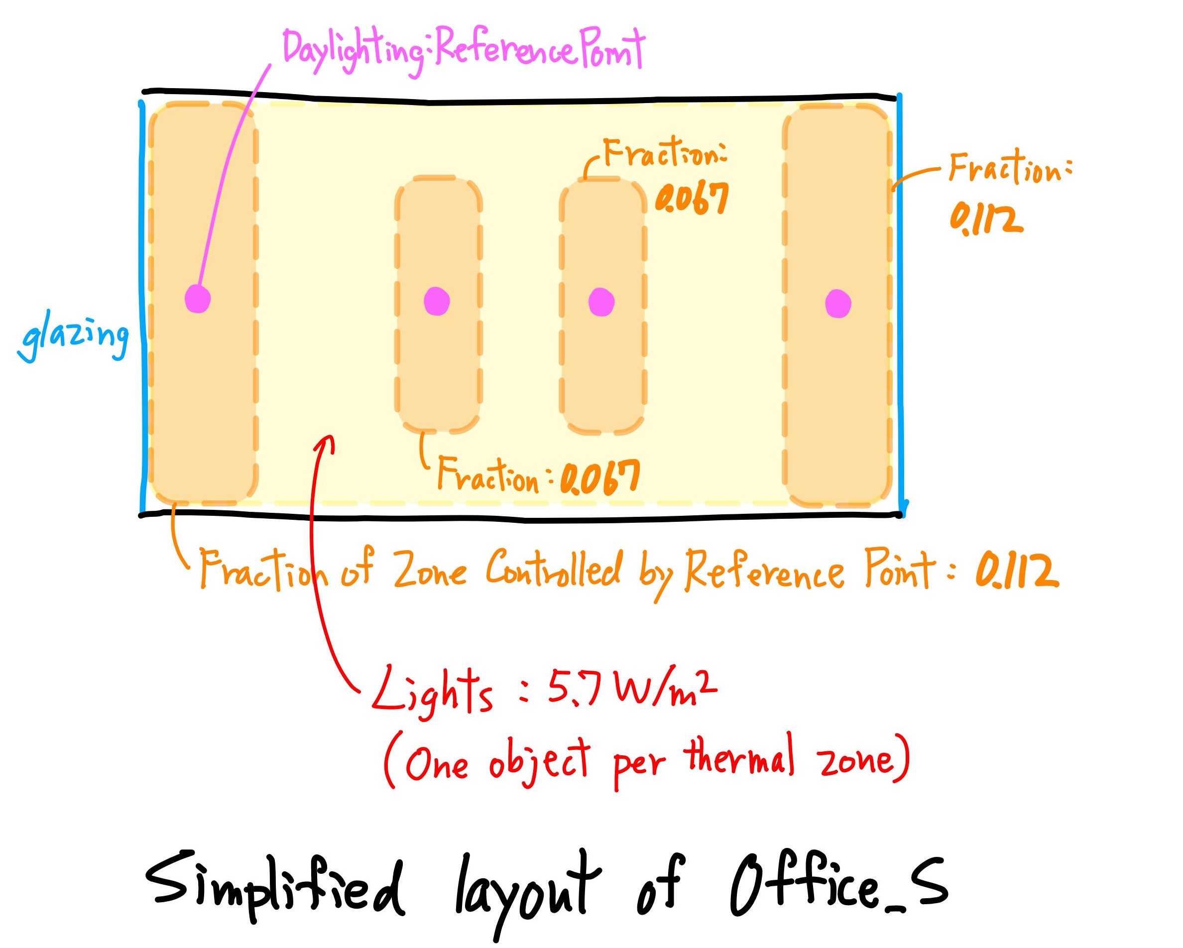
Below is the simplified layout of Office_S. I think One thermal zone can have multiple Daylighting:ReferencePoints, and the lighting area controlled by each Daylighting:ReferencePoint is defined by Fraction of Zone controlled by Reference Point. Each daylighting control is independent. So, it does not make sense to increase lighitng power by adding Daylighting:ReferencePoint.
Now, Daylighting Method is SplitFlux. I/O Reference says "Note when the DElight Daylighting Method is used, that the sum of all Reference Point control fractions must equal 1 to obtain correct overall results.", so I don't use DElight because the sum of all Reference Point control fractions in each thermal zone is less than 1 in my model.


@Keigo have you tried a 4th case: Daylighting control in perimeter zone and interior zone (no TDD)? The daylight sensors in the interior zone will likely not receive enough daylight to reduce interior lighting, but that would help you confirm that daylighting controls are defined correctly.
It may also help to plot interior vs. perimeter lighting separately for each case. If you have made one zone with one
Lightsobject, you could "split" that into two lights and adjust daylighting controls, then add output variables for power of eachLightsobject.Thank you for your advice!. I ran the 4th case, and eddited my Question.
For your second comment, yes, I have made one zone with one
Lightsobject, but How can I "split" that into two lights? Do you meas that I should split one thermal zone into two thermal zones (Perimeter thermal zone and Interior thermal zone)? I'd rather not because HVAC zoning is not separated by perimeter area and interior area in my model..."Split" lights => define multiple cases of the
Lightsobject type for one zone ie. a perimeter lights vs. an interior lights. This would also require setting different End-Use Categories for each lights ("Perimeter Lighting" vs. "Interior Lighting") to be able to plot them separately usingOutput:Meterobjects.I suggested "splitting" the lights as more of a debugging step to explain the lighting power trends, so trying to match building design isn't critical. We just want to have a version of this model that can generate output variables/meters that will help explain the trends you are seeing.