VRF with constant curves has COP < 1.0

!!!THIS ISSUE SHOULD BE FIXED IN ENERGYPLUS 9.3!!!
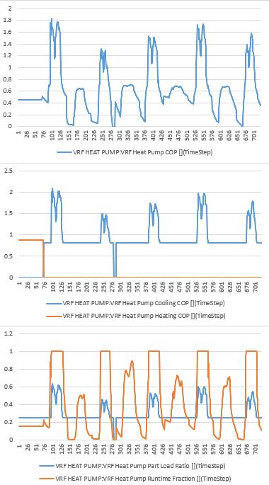
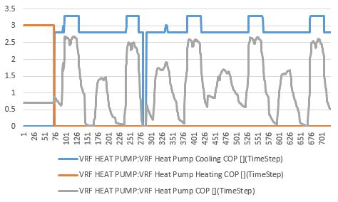
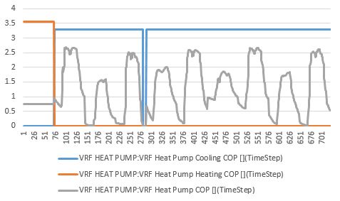
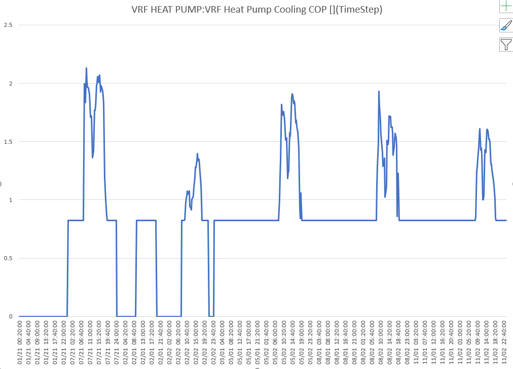
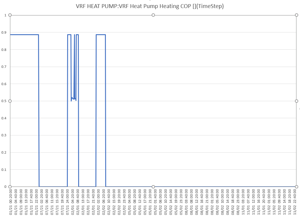
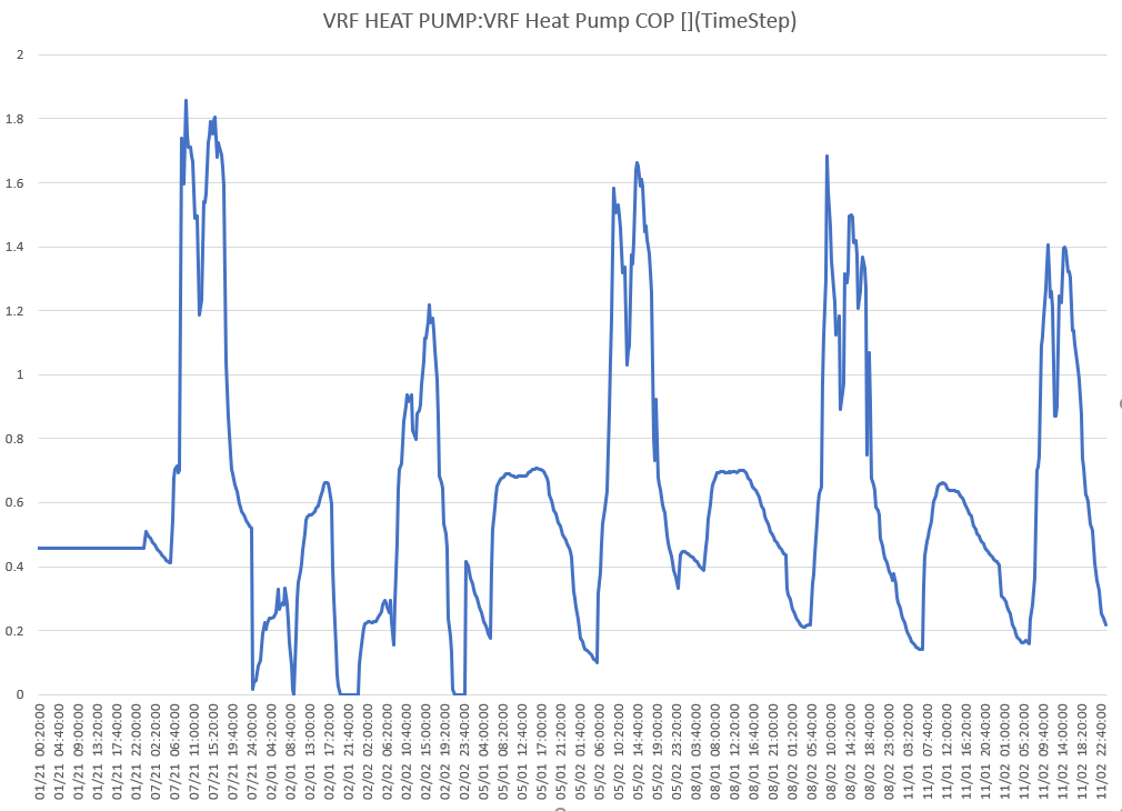
I took the DOAtoVRF.idf example file and modified all the curves to be constant, then graphed the COP for the design days and two days in each season. Since the curves are constant and no longer depend on anything, why is the COP changing so much in the simulation?
The COPs are also way too low for heating and cooling, which are 3.5484 and 3.2917 in the IDF, but less than 1.0 and 2.5 in the simulation.
What inputs are left in the VRF object that can be changed to get a VRF system in which there is zero dependence on indoor and outdoor conditions? In other words, how can I get the COP to be a step function?
Here is a google drive link for the IDF and Excel graphs. I discovered this when comparing the energy use of an AC/Furnace, HeatPump, and VRF system for the same building. The energy use for heating and cooling make sense for the AC/Furnace and HeatPump cases, but the VRF system uses about 4/3 as much energy for cooling and 3 times as much energy for heating compared to the HeatPump case, and the COP of the VRF is higher than the HeatPump! This is using the EnergyPlus example VRF curves as well as constant curves. Something is super duper wrong with my IDF, and I've run out of ideas on what could be wrong.
AirConditioner:VariableRefrigerantFlow,
    VRF Heat Pump,           !- Heat Pump Name
    VRFCondAvailSched,       !- Availability Schedule Name
    autosize,                !- Gross Rated Total Cooling Capacity {W}
    3.2917,                  !- Gross Rated Cooling COP {W/W}
    -5,                      !- Minimum Outdoor Temperature in Cooling Mode {C}
    43,                      !- Maximum Outdoor Temperature in Cooling Mode {C}
    VRFCoolCapFT,            !- Cooling Capacity Ratio Modifier Function of Low Temperature Curve Name
    VRFCoolCapFTBoundary,    !- Cooling Capacity Ratio Boundary Curve Name
    VRFCoolCapFTHi,          !- Cooling Capacity Ratio Modifier Function of High Temperature Curve Name
    VRFCoolEIRFT,            !- Cooling Energy Input Ratio Modifier Function of Low Temperature Curve Name
    VRFCoolEIRFTBoundary,    !- Cooling Energy Input Ratio Boundary Curve Name
    VRFCoolEIRFTHi,          !- Cooling Energy Input Ratio Modifier Function of High Temperature Curve Name
    CoolingEIRLowPLR,        !- Cooling Energy Input Ratio Modifier Function of Low Part-Load Ratio Curve Name
    CoolingEIRHiPLR,         !- Cooling Energy Input Ratio Modifier Function of High Part-Load Ratio Curve Name
    CoolingCombRatio,        !- Cooling Combination Ratio Correction Factor Curve Name
    VRFCPLFFPLR,             !- Cooling Part-Load Fraction Correlation Curve Name
    autosize,                !- Gross Rated Heating Capacity {W}
    ,                        !- Rated Heating Capacity Sizing Ratio {W/W}
    3.5484,                  !- Gross Rated Heating COP {W/W}
    -20,                     !- Minimum Outdoor Temperature in Heating Mode {C}
    20,                      !- Maximum Outdoor Temperature in Heating Mode {C}
    VRFHeatCapFT,            !- Heating Capacity Ratio Modifier Function of Low Temperature Curve Name
    VRFHeatCapFTBoundary,    !- Heating Capacity Ratio Boundary Curve Name
    VRFHeatCapFTHi,          !- Heating Capacity Ratio Modifier Function of High Temperature Curve Name
    VRFHeatEIRFT,            !- Heating Energy Input Ratio Modifier Function of Low Temperature Curve Name
    VRFHeatEIRFTBoundary,    !- Heating Energy Input Ratio Boundary Curve Name
    VRFHeatEIRFTHi,          !- Heating Energy Input Ratio Modifier Function of High Temperature Curve Name
    WetBulbTemperature,      !- Heating Performance Curve Outdoor Temperature ...